


Contact Us
Temperature Transmitters
Wire Harnesses
Temperature Sensors
Fiber Optic Sensor Systems (Partner Company)
Thermocouple/Extension Wire
Temperature and Process Controllers
Specialty Metals


Whitepapers / A ultra fast thermocouple used to measure: squibs, ignitors, propellants, and rocket nozzles
The temperatures produced by the various components in the propulsion system of rockets and missiles determine the performance of the rocket. Since these temperatures occur very rapidly and under extreme conditions, standard thermocouples fail before any meaningful temperatures are measured. This paper describes the features of a special family of high performance thermocouples, which can measure these transient temperatures with millisecond response times and under the most severe conditions of erosion. Examples of igniter, propellant and rocket nozzle temperatures are included in this paper. Also included is heat flux measurements made by these sensors in rocket applications.
The special thermocouple used in these tests was designed and built by Nanmac Corporation. It is referred to as the “Self- Renewing“ or “Eroding“ Thermocouple. This design uses standard dissimilar thermocouple elements precisely the same as the conventional thermocouples mentioned above. However, in the vicinity of the “hot“ measuring junction, the sensing tip details are unique. The round wires of the dissimilar metals are ground and flattened into thin ribbons of about 0.0015/0.002 in thickness. These ribbon elements are electrically insulated from each other and the thermowell (thermocouple housing) by sheets of thin dielectric insulation of about 0.0002 inch thickness. This “sandwich“ of ribbon elements and thin dielectric insulation is then placed between a split-tapered insert and pressed into a mating tapered hole in the thermowell Fig. (1). The excess material is then machined off and the surface of the thermowell is polished with an abrasive cloth or sandpaper until smooth. The process of grinding and polishing the surface forms the “hot“ measuring junction automatically. The dielectric insulation between the two dissimilar ribbons is so thin that metallic whiskers of one ribbon (thermocouple) element bridge the dielectric and make hundreds of microscopic friction welded junctions which are parallel to one another thus forming one composite measuring junction, the junction is formed only on the surface of the housing, therefore exact location is known to the user. Any subsequent erosion of the surface (rocket blast, grinding, interface erosion) of the thermowell simply forms new junctions while removing the old junctions. Hence its name, “Self-Renewing (SR) Thermocouple.“ The sensing tip can be machined to match any contour. Additional information on the “Self-Renewing“ thermocouple is available.

Fig. (2) is an actual oscilloscope screen shot of the pressure and temperature trace lines of the leading edge of shock wave. The SR Thermocouple and a high frequency pressure gage were located at the same longitudinal location in the shock tube. The shock tube was evacuated and filled with a combustible mixture and then electrically ignited at one end. The temperature and pressure were recorded as the detonation wave passed this location. The recorded temperature is the precise temperature seen by the inner wall surface as the wave passed by. A response time of eight (8) microseconds is recorded on this test. The actual measured temperature change is 225 degrees in eight (8) microseconds. This is equivalent to a rate of over 28,000,000 degrees Fahrenheit per second. The velocity of the detonation wave, in addition to its temperature data can thus be recorded by a series of thermocouples located longitudinally in the shock tube. The slight oscillations on the traces were caused by a combination of the mechanical vibration and the electromagnetic field associated with the detonation wave.
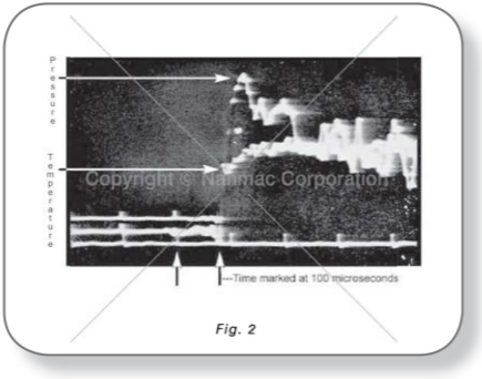
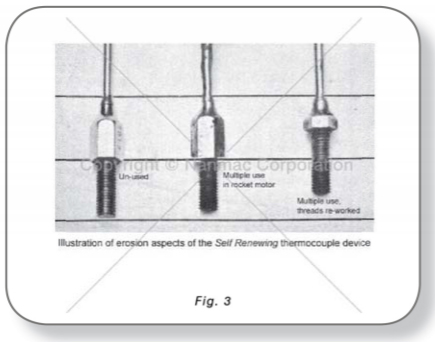
Fig. (3) is a photograph of three identically constructed SR thermocouples. The one on the left is a new unused unit while the other two have been used repeatedly in a rocket nozzle. Note that the overall length has decreased with usage. Note also that new threads were machined on the far right unit. Both units recorded the surface temperatures continuously while the sensing tip was eroding away. All standard SR thermocouples will operate until about 3/8 has eroded off their sensing tips.
Typically, all contact temperature sensors (RTD’s, thermocouples, etc.) provide the user with data that exhibits the temperature of the sensor itself, as its environment affects it. Therefore, the thermal properties of the sensors must match those of the test wall otherwise, the temperature of the test wall is only assumed, rather than measured. By specific design, the SR thermocouple is made from the same material as the test wall i.e. graphite phenolic, EDPM rubber, etc. Hence, the temperature that is measured is ultimately that of the test wall material. Several tests have been conducted to demonstrate the effect using materials for the thermowell other then those of the test wall. Results of one such test conducted by the U.S. Navel Propellant Plant Fig. (4) demonstrates the large differences in the peak temperature measured at the surface of the wall, simply by changing the thermocouple housing material. The thermocouple geometry, location within the test chamber, thermocouple elements and the data acquisition are the same, the only difference between the two sensors is the thermocouple housing material.

In instances where the gas or flame temperature is desired, the split tapered insert is made from thermally isolating materials to reduce conduction between the test wall and the gases. This then provides a “thermally isolated“ junction and the actually temperature of the gases beneath the laminar layer formed at the wall surface are those that are measured, rather than the wall surface temperature.
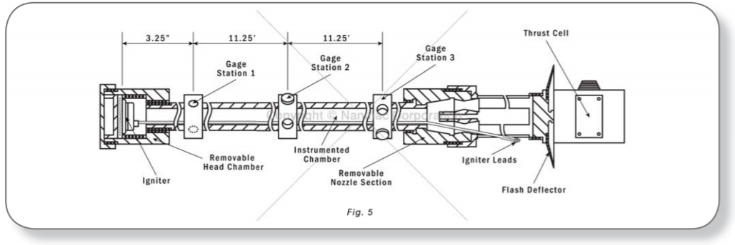
Our fighter pilots were complaining that their rockets would occasionally make 60° or 90° turns in front of the fighter planes. They were concerned that they would fly into their own rockets! Also, they complained that there were too many rockets that had intermittent ignition, delayed ignition, etc. Unless we could fix these problems, the NAW was going to scrap millions of these rockets. A simulated rocket was designed which had the same internal dimensions as the real rocket. This simulated rocket motor contained a removable igniter chamber and a removable nozzle section. The removable feature allowed us to condition these sections at various temperatures from —40° to + 140°F. The motor chamber contained three gage stations — each with a pressure gage and thermocouple inlets. Fig. (5) is a drawing of this simulated rocket chamber.
Using this thermocouple design, the Naval Propellant plant characterized squibs based on the temperature and heat flux data. The squibs from small rockets (2.75 rockets) produced a maximum of 900°F flame temperatures in less than 174 sec. (250 ms). Subsequently a number of fully assembled igniters were fired (Ref. 2) using a full-sized dummy rocket with a wood grain simulated propellant charge to observe the temperature distribution pattern in the rocket.
The igniter in most rockets and missiles consists of two main items — i.e., the squib and the main igniter charge. The squib consists of an electrical resistance wire over which is coated a combustible charge — usually black powder and magnesium. When the firing switch is activated, an electrical current passes through the squib, which in turn is heated, and the combustible coating is ignited which then ignites the main charge. The main charge then explodes the igniter container and a hot flame is then sent to the main propulsion charge. During acceptance, a number of squibs are tested at various temperatures from about -40°F to + 140°F. The usual parameters that are measured include time to ignition and occasionally the pressure characteristics. Finally, a number of squibs are tested with the assembled igniters to observe their ignition characteristics. Usually no temperature or heat flux data are measured because of the lack of suitable sensors.
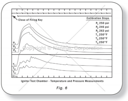
Both pressure and temperature sensors were installed at three locations along the length of the propellant chamber. A typical set of test records is shown in Fig. (6). Note that all temperature traces indicated a rise in temperature before the pressure gages in the corresponding longitudinal locations. The delay in the response of the P/T gages was caused by the time required for the pressure wave to travel through the grease column in the bourdon tubes. Also, note that one can obtain the velocity of the flame front from one location to the next from the T/t traces.
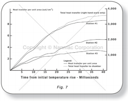
Test equipment and mathematical procedure used to calculate the rate and total heat-transfer data were evaluated by firing several randomly chosen igniters in the chamber after it had been assembled with closed end nozzle fixture. A comparison of the total heat thus measured with the mean standard heat-of- explosion values of similar igniters showed that there was no statistically significant difference between the data obtained by the two different methods. Once this had been established, the test chamber was fitted with standard nozzle assemblies, and additional data were obtained. In these tests, the igniters were subjected to the various nozzle closure effects normally experienced in actual use. The usual ballistic characteristics such as ignition delay, burning time, maximum pressure, and pressure-time integrals were determined from the pressure oscillograms. The rate of heat transfer and the total heat transfer from the igniter to the wall of the test chamber were calculated from the temperature oscillograms. Fig. (7) contains the average of several igniter-firing tests.
The heat transfer data indicate that an average of 3,453 calories was transferred from the igniters to the chamber. Since standard closed bomb measurements revealed that an average of 7,764 calories was available from the igniters, it is apparent that 4,311 calories were lost via the nozzle. Therefore, slightly over 55% of the total energy output of the igniters was actually not available to the grain for ignition. The rubber seals in the four nozzles had become hardened through age (storage) and were blown out by the igniter blast erratically. Since all of the seals did not blow out at the same instant, the rocket made erratic turns. They not only caused a safety problem; but also, veered off target just prior to impact.
The principal purpose of the igniter is to ignite the propellant charge reliably over the temperature range of its intended use — usually from -40°F to +140°F. During the ignition phase of propellant charges, two things are most important — i.e., the igniter must deliver a sufficient heat flux to the grain surface to ignite. Also, the pressure created by the ignition phase must have a minimum value to sustain burn once it has started and the pressure must not exceed a maximum value so that the rocket does not explode. Unfortunately, the specifications of rocket propellants only specify the pressure values but do not typically specify any temperature or heat flux values. The ideal igniter should produce a rate of heat flux output that is gradually increased and sustained for a sufficient duration so that the heat output of the burning surface of the grain matches the heat output of the igniter. If this does not occur, you may experience delayed ignition, intermittent chuffling, etc. While this is occurring, the igniter pressure must meet the minimum threshold pressure to sustain ignition and must not exceed the maximum pressure for safety. If the igniter produces a high-pressure wave, it will hammer the grain against the rocket chamber wall or the nozzle fixture. This in turn will cause the grain to crack thus producing a much larger surface area, which, in turn, will create excessively high pressures such that the nozzle cannot handle the gases. Some rocket motors are equipped with thrust termination ports which act as safety valves to release excessively high-pressures before the rocket motor blows up.
Rocket motors are usually tested in the tie-down fixtures inside a concrete firing bay. The thrust cells are usually attached at the front end of the motor. Several SR thermocouples were installed in a second nozzle half-ton charge motor to measure the inner surface temperatures at several locations during captive firing tests (Ref. (3). The calculated combustion temperatures of the propellant used in these tests is in excess of 6000°F. All thermocouples use W/W-26%Re-elements. Fig. (8) is a typical temperature trace of a “Self-Renewing“ thermocouple located 2-1/2 inches forward of the nozzle throat.

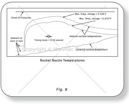
The nozzle of a Terrier Booster was drilled and tapped with appropriate holes to accommodate two thermocouples at the same longitudinal plane in the nozzle but displaced radially 180°. The thermocouples were located at the surface of the nozzle throat. When installed in the nozzle, the sensing tips of the thermocouples were aligned flush with the inner wall of the nozzle so that the gas flow was not disturbed in any way. Extreme caution was exercised in aligning the thermocouples such that they were flush with the wall as any protrusion or recess of the thermal junction with respect to the wall will cause erroneous temperature measurements. In addition to the two thermocouples at the inner surface of the nozzle throat, a common welded thermocouple was attached to the exterior surface at the same location to measure the external temperature A reproduction of the actual test oscillogram of one such firing test is shown in Fig. (9). The maximum temperature changes recorded by the two nozzle-throat thermocouples were 2230°F respectively.
Maximum difference between the two temperature traces is less than 2% throughout the complete test record, considered excellent for this type of measurement.
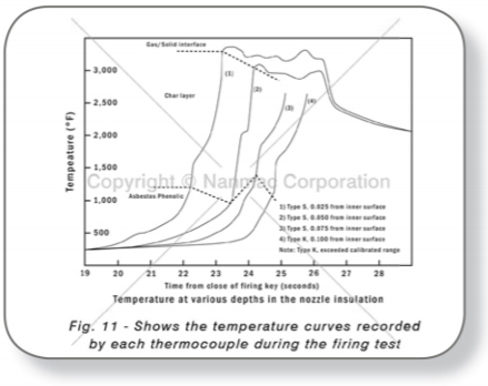
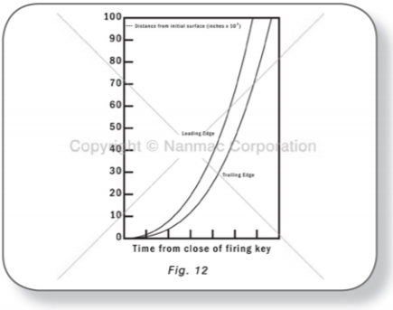
In another type of rocket motor Fig. (10) (Polaris Scale Model Fiberglass Motor), four “Self- Renewing“ thermocouples were installed in the asbestos-phenolic (RPD 150) insulation of the exit cone at depth of 0.025, 0.050, 0.075 and 0.100-inch from the inner surface. All thermocouples were located in the same longitudinal plane but again, displaced radially. Post-firing examination revealed that erosion had exposed the sensing surface of all four thermocouples. The thermocouple which was originally closest to the inner surface was shortened about 1/8 inch.
The “Self-Renewing“ thermocouple has demonstrated that it can measure the instantaneous temperature and heat flux characteristics in all phases of the rocket motor propulsion system. Its unique features have been used to measure the temperatures created by squibs, igniters and rocket propulsion systems. It has also been used to define the erosion characteristics of rocket nozzles and insulations: temperature characteristics of rocket propulsion systems can now be measured and analyzed.
Reference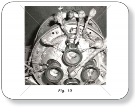
© 2025 Nanmac Corporation
